Revolving Joinery
Classic timber joints were invented and refined over hundreds of years during the pre-industrial era. They have been defined by the available tools and therefore mirror their fabrication process as well as their function within a structure. Today, the range of tools has expanded to computer-numerically-controlled (CNC) milling, which has been transformed by advances in computational design techniques and robotics. These advances allow previously unattainable geometrical freedoms that allow joints to be designed in a way such that they better take advantage of the properties of the particular structural typology in which they are being implemented.
While there has been extensive research in the development of joints for beams, joints for lightweight shell structures have not yet been pursued to the same extent. Lightweight shell structures feature relatively low bending moments due to their thin profile, which suggests that a joint whose locking mechanism is by rotation would be the most suitable for this type of structure. Thus the aim of this project was to design and fabricate such a revolving timber joint.
In collaboration with André Kauffman and Alexandre Mballa-Ekobana

The design of the rotational joint started with looking at a basic finger joint and seeing how it could be improved to handle more forces. The main goal of the design was to have the joint be able to take compression, tension, horizontal shear, and vertical shear forces.

Design development of the revolving joint
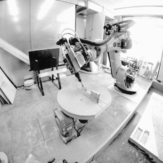
Once the design concept of the joint was determined based on the forces it needed to resist, the fabrication of the joint was investigated in consideration of the tools available. It was understood that the creation of the joint would involve a multistage subtractive manufacturing process using a KUKA industrial robot with milling bits as its end effector. Based on the material subtractions that had to be made, the milling paths were generated in Grasshopper using the Sandbox CNC plugin and simulated to validate that all points were attainable using inverse kinematics. Circular paths were generated that took the form of point clouds and vectors at which the bit was supposed to approach the part at each point. The subtraction of the stock material according to the fabrication path was then modeled using boolean operations, which were also used to check if the two parts would theoretically fit.
Male sequence
Female sequence

Modeling of subtraction sequences
At this point, it was time to mill the joint from 21mm plywood plates in the Robotic Fabrication Laboratory at the Institute for Computational Design & Construction.
-01.jpg)


